- 您现在的位置:买卖IC网 > Sheet目录510 > SI4777-A20-GM (Silicon Laboratories Inc)IC RCVR AM/FM CE HD-RADIO TUNER
Si4770/77-A20
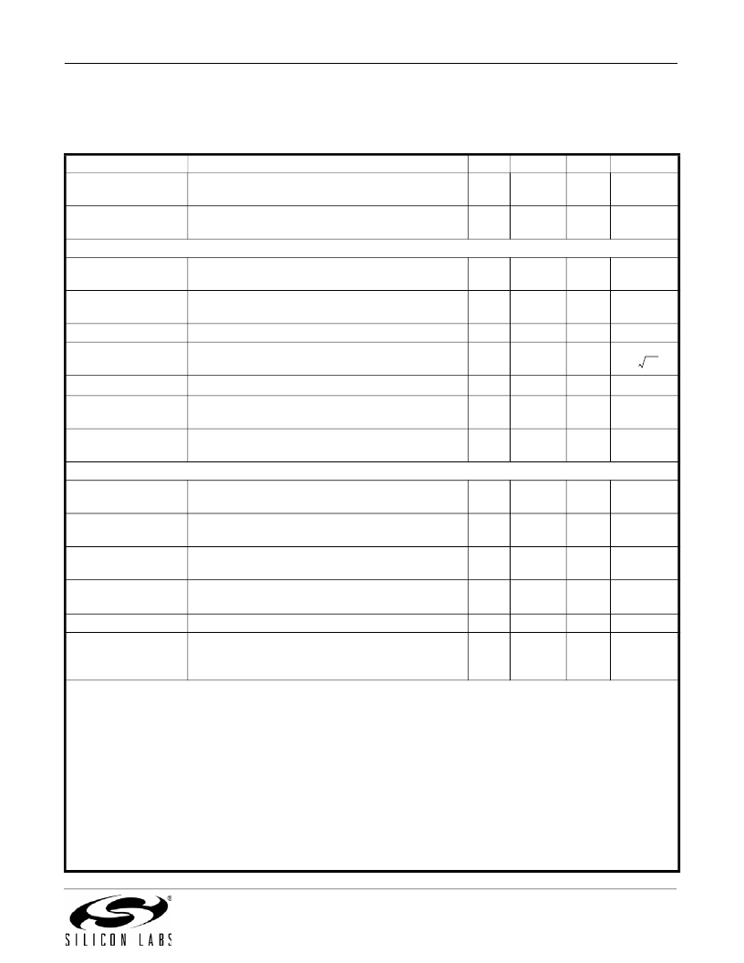
Table 7. FM Receiver Characteristics (Continued)
(T AMB = –40 to 85 °C, V A = 4.5 to 5.5 V, V D = 2.7 to 3.6 V, V IO1 = 1.7 to 3.6 V, V IO2 = 1.2 to 3.6 V. Typical values measured at
T AMB = 25 °C, FM modulation (L = R), F MOD = 1 kHz, F DEV = 22.5 kHz, Deemphasis = 75 μsec, RF level = 60 dBμV, and
F RF = 98 MHz in application circuit unless otherwise specified)
Parameter
FMO Output
Resistance 3
FMO Output
Capacitance 3
Test Condition
Nominal FMI to FMO gain = 8 dB,
Source load = 50 ?
Min
—
—
Typ
125
2
Max
—
—
Unit
?
pF
Dual Receiver Mode
FMI Input
Resistance 7,3
FMI Input
Capacitance 3
—
—
100
1.5
—
—
?
pF
FMI Return Loss 3
FMI Input Referred
Noise 3
64 MHz < F < 108 MHz
—
—
15
1.20
—
—
dB
nV/ Hz
FMI LNA IP3
FMO Output
Resistance 3
3,8
Blockers at 400/800 kHz offset, Max Gain
Nominal FMI to FMO gain = 8dB,
Source load = 50 ?
—
—
126
250
—
—
dBμV
?
FMO Output
Capacitance 3
—
2
—
pF
Audio Outputs: Pins LOUT and ROUT
Audio Frequency
Response Low 1,2
Audio Frequency
Response High 1,2
Output Load
Resistance 3
Output Load
Capacitance 3
Output Voltage
Power Supply
±3 dB
±3 dB
At LOUT and ROUT pins
At LOUT and ROUT pins
Deviation = 22.5 kHz
100 Hz ripple on power supply lines.
—
15
10 k
—
99
—
—
—
—
—
112
45
30
—
—
50
125
—
Hz
kHz
?
pF
mVRMS
dB
Rejection Ratio
(PSRR) 3
Ripple voltage = 100 mV PP of power supply
voltage
Notes:
1. Guaranteed by characterization.
2. Measured at T AMB = 25 °C.
3. Guaranteed by design.
4. IP3 measured at the FMXIP and FMXIN pins reflects IP3 for mixer stage and all subsequent downstream blocks.
5. Refer to FM test circuit in Figure 5.
6. No A-weighting. Noise integrated from 30 Hz to 15 kHz for audio SINAD and SNR measurements.
7. Input resistance is software configurable.
8. IP3 measured at the FMI input pin reflects IP3 for FMI LNA stage.
9. RDS Synchronization Persistence is the minimum RF level at which the tuner loses synchronization to the RDS PI code
as the RF level decreases from high to low levels.
10. RDS Synchronization Stability is the minimum RF level at which the tuner achieves synchronization to the RDS PI code
as the RF level increases from low to high levels.
11. Noise integrated from 30 Hz to 120 kHz for audio SINAD and SNR measurements.
Rev. 0.9
15
发布紧急采购,3分钟左右您将得到回复。
相关PDF资料
SI4804CDY-T1-E3
MOSFET 2N-CH 30V 8A SO8
SI4808DY-T1-GE3
MOSFET N-CH/SCHOTTKY 30V 8SOIC
SI4812BDY-T1-GE3
MOSFET N-CH D-S 30V 8-SOIC
SI4814BDY-T1-GE3
MOSFET N-CH/SCHOTTKY 30V 8SOIC
SI4816DY-T1-GE3
MOSFET N-CH DUAL 30V 8-SOIC
SI4818DY-T1-GE3
MOSFET N-CH DUAL 30V 8-SOIC
SI4830ADY-T1-GE3
MOSFET DUAL N-CH 30V 5.7A 8-SOIC
SI4834BDY-T1-GE3
MOSFET DUAL N-CH 30V 5.7A 8-SOIC
相关代理商/技术参数
Si4777-A20-GMR
功能描述:射频接收器 Hi-Performance CE AM/FM Rcvr/HD-Tuner
RoHS:否 制造商:Skyworks Solutions, Inc. 类型:GPS Receiver 封装 / 箱体:QFN-24 工作频率:4.092 MHz 工作电源电压:3.3 V 封装:Reel
SI4778DY
制造商:VISHAY 制造商全称:Vishay Siliconix 功能描述:N-Channel 25-V (D-S) MOSFET
SI4778DY-T1-E3
功能描述:MOSFET 25V 8.0A 5.0W 23mohm @ 10V RoHS:否 制造商:STMicroelectronics 晶体管极性:N-Channel 汲极/源极击穿电压:650 V 闸/源击穿电压:25 V 漏极连续电流:130 A 电阻汲极/源极 RDS(导通):0.014 Ohms 配置:Single 最大工作温度: 安装风格:Through Hole 封装 / 箱体:Max247 封装:Tube
SI4778DY-T1-GE3
功能描述:MOSFET 25V 8.0A 5.0W 23mohm @ 10V RoHS:否 制造商:STMicroelectronics 晶体管极性:N-Channel 汲极/源极击穿电压:650 V 闸/源击穿电压:25 V 漏极连续电流:130 A 电阻汲极/源极 RDS(导通):0.014 Ohms 配置:Single 最大工作温度: 安装风格:Through Hole 封装 / 箱体:Max247 封装:Tube
SI4779CY
功能描述:电源开关 IC - 配电 N-Ch 30V RoHS:否 制造商:Exar 输出端数量:1 开启电阻(最大值):85 mOhms 开启时间(最大值):400 us 关闭时间(最大值):20 us 工作电源电压:3.2 V to 6.5 V 电源电流(最大值): 最大工作温度:+ 85 C 安装风格:SMD/SMT 封装 / 箱体:SOT-23-5
SI4779CY-E3
功能描述:电源开关 IC - 配电 N-Ch 30V RoHS:否 制造商:Exar 输出端数量:1 开启电阻(最大值):85 mOhms 开启时间(最大值):400 us 关闭时间(最大值):20 us 工作电源电压:3.2 V to 6.5 V 电源电流(最大值): 最大工作温度:+ 85 C 安装风格:SMD/SMT 封装 / 箱体:SOT-23-5
SI4779CY-T1-E3
功能描述:电源开关 IC - 配电 Hi-Side N-Channel RoHS:否 制造商:Exar 输出端数量:1 开启电阻(最大值):85 mOhms 开启时间(最大值):400 us 关闭时间(最大值):20 us 工作电源电压:3.2 V to 6.5 V 电源电流(最大值): 最大工作温度:+ 85 C 安装风格:SMD/SMT 封装 / 箱体:SOT-23-5
SI477x
制造商:SILABS 制造商全称:SILABS 功能描述:Si477X EVALUATION BOARD USERa??S GUIDE
